DIY F/Stop Timer Construction
If you build this, please contact me (email address is in the headers of all the source files) as I'd like to have some idea of how many of these are out there. Of course if you have suggestions or bug reports, please send them in too.
Parts and Resources
You will require:
- An Arduino with ATmega328 (e.g. Duemilanove or Uno) and the development environment; I have been using version 1.0.5 with avr-gcc 4.8.2,
- the source code: v0.6 for Rev.B PCBs or v0.5 for Rev.A PCBs,
- the schematic and board design or schematic PDF (Rev.B),
- a 16x2 red-backlit HD44780-compatible LCD,
- a 4x4 matrix keypad with alphabetics on the keys,
- a rotary encoder with press-switch,
- a mains-rated relay, preferably SPDT and rated for about 10A,
- a TSL235 light sensor (optional),
- other minor components and hardware; see detailed BOM below
- a USB charger to power it and a case to put it all in,
- tools and electronics-hacking skills (sidecutters, wire strippers, soldering iron, vice, Dremel with PPE, etc)
This was my first attempt at using KiCad so library files ended up spattered all over my filesystem. I've tried to include everything in the above zipfile but if there's something missing (note the modules and library directories in the zip; they are critical) and it won't build then email me. The plot subdirectory contains gerbers ready for PCB manufacture.
You don't need to use the official PCB, you can easily make up the circuit using an Arduino Prototyping Shield (about $3 on eBay) and a couple of hours with the soldering iron.
Detailed BOM
- f/stop timer PCB Rev.B
- Arduino Duemilanove, Uno or any clone thereof with an ATmega328; the ATmega168 has insufficient flash space
- 16x2 red LCD, the PCB layout assumes you have a JHD162A
- Rotary Encoder7, link
- 4x4 matrix keypad12, Jaycar SP0772, Grayhill 96BB2 at Mouser or equivalent
- Mains-rated output relay, opto-coupled8, e.g. PowerSwitchTail (NB voltage variations!) or SSR or SSR module, or
- mains-rated SPDT mechanical relay9
- TSL235R light sensor11, link (light-to-frequency convertor)
- 2 of 40-way breakable SIL pin headers, link
- 1 of 16-way breakable SIL pin female headers, link
- 2 of BC5482
- 1N4004 or 1N4148 diode3
- 4 of 6k8 resistors, 1/8W or 1/4W; values as low as 3k3 are acceptable
- 100n monolithic capacitor
- 10k trimpot, Bourns 3362 style
- 2 of 1k resistor2
- backlight current-limit resistor4
- 2 of 16-way female ribbon IDC connectors, eg mouser 571-1658621-3; these are like IDE hard drive connectors but 16 pins instead of 40
- ~15cm of 16-way 0.05"-pitch ribbon cable (e.g. cut up an old hard drive cable)
- 2.5mm stereo socket11,13
- 1m of 3-core cable (e.g. phone cable), terminated with 2.5mm tip/ring/sleeve plug11,13
- 3.5mm mono socket10
- heavy-duty NO momentary foot switch10 with cable, terminated with 3.5mm male tip/sleeve plug
- USB charger1 or
- 5VAC 5VA transformer5
- W04 bridge rectifier5
- 470uF 15V electrolytic capacitor5, 0.2" lead pitch, ~10mm diameter
- 10mm and 5mm threaded nylon PCB standoffs for M3 screws6
- M3 machine screws in appropriate lengths 6
- rubylith to cover LCD, if your LCD backlight is not paper-safe
- prototyping jumpers with female ends (link) and a willingness to cut them up - for connecting the relay, footswitch panel-socket, etc to the PCB pin-headers
- a metal case to safely contain all of the above, properly earthed
Notes:
- Use phone charger if powering timer from USB
- One for output relay (optional), one for backlight
- Required only when driving magnetic output relay9
- use wire link for JHD162A, otherwise select resistor according to your display's backlight requirements
- Required only when powering from the AC mains input
- For bolting the LCD, timer PCB, Arduino and case in a stack.
- Number of clicks per revolution is irrelevant. All that matters is that it has three pins on one side (common-centre and two quadrature lines) and two pins on the other side for the push-switch. Different manufacturers have all sorts of different relationships between detents (clicks) and the quadrature transitions, but they should all be compatible by setting the right options in the code and maybe bending the stress-relief solder-tabs a bit
- use the OUTTTL pins on the timer PCB, no further isolation required. A powerswitchtail is strongly recommended for those without mains electricity safety training
- relay must have 5VDC coil drawing max 80mA, unless you want to build a much more-complicated power supply; use an SPDT relay to control both the enlarger and safelight
- Required if you want to support an external foot/elbow/knee switch
- Required if you want baseboard metering; the timer will work fine without metering
- Look for a keypad with SMS alphanumerics under the digits; it makes it far easier to type in exposure description strings. Lots of cheaper keypads are available from eBay without the lettering though and they will work OK
- Required to connect the light-meter probe
Practically everything can be bought from either eBay or your local electronics store; you shouldn't need to make an order to a huge online place like mouser/digikey but you can if you want.
Construction Process
From the source code archive, copy the Keypad, RotaryEncoder, FreqMeasure and FstopTimer directories to your Arduino Libraries directory and the fstop_driver (top level sketch) to your sketchbook. Make sure it compiles successfully.
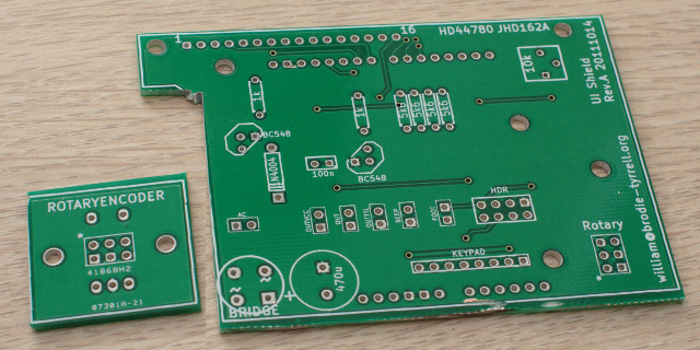
Separate the PCB using a dremel, hacksaw or guillotine, following the lines as marked. You will need the main PCB and the rotary encoder PCB at this stage; put the TSL230/TSL235 PCBs aside for now. You may want to trim some more off the rotary encoder PCB in order to make it fit in your case, just don't encroach on where the pins get soldered.
The power supply components on the board (bridge and 470uF cap) should be left off if you're running on USB power or via the DC jack on the arduino, but are needed if you want to run from a 5VAC transformer. You could also use a 5V/0.5A switchmode supply module connected directly to VCC.
If using a TTL-compatible output device, e.g. anything with an optocoupler like an SSR module, connect it to the OUTTTL header and leave off the relay driver components (1k resistor, BC548 and 1N4004 to the left). Otherwise, connect your relay coil to OUT and short the OUTVCC header to set the relay's coil voltage to 5V. If the relay is not 5V, you can supply the higher voltage via the OUTVCC header - see the schematic for details. Use the prototyping jumper wires to make the connection from the timer PCB to your relay module.
If you want the timer to control your safelight (off during exposures for better image visibility and exposure metering), you must use an SPDT or DPDT relay. Connect your safelight using the NC connections and the enlarger using the NO connections, with power at Common. Don't forget to connect your chassis to mains ground for safety, unless you are using a sealed relay module like powerswitchtail.
If you're using a mechanical relay and directly soldering mains connections to its pins, pot all the connections after soldering using hot glue or epoxy; this provides strain relief and insulation - a great improvement to safety!
The footswitch (NO momentary) is wired in parallel with the press-switch on the rotary encoder. Mount a 3.5mm panel socket on your case and connect it to the FOOT (tip) and GND (sleeve) pins on the PCB using the prototyping jumper wires. This is the means by which the timer PCB is grounded; if you don't have a footswitch socket then you should connect a separate wire from one of the GND pins on the timer to your chassis. You must not rely on an external (e.g. phone charger or DC wall-wart) for safety grounding as it may be unplugged!
The collector resistor for the LED backlight is required ONLY if the LCD module does not have one on-board. If you are using a JHD162A or any other module with included resistors that wants 5V for the backlight, then use a wire link here instead of a resistor. It's the 1k resistor closest to the centre of the PCB. If your backlight is raw LEDs with no current-limit resistor provided on the LCD module, choose whatever value your backlight requires (for a 5V supply) and install it here.
The rotary encoder gets mounted on a little daughter board and connected to the main board using 6 pins of header+sockets; this is to raise it to the front panel, level with the LCD. Solder the sockets onto the board first (you can't get to them once the encoder is soldered in!). You will need to put a small piece of paper or plastic under the encoder (they usually have a metal underside) to stop it shorting out the socket pins that it's right on top of.
Solder a row of pins onto the keypad. Make up a ribbon cable to go between the timer PCB and keypad - probably about 10cm depending on your case layout. To crimp the IDC (insulation displacement) connectors onto the ribbon, use a small vise: gently hold the connector in the vise jaws without compressing it, insert the cable and ensure it's properly lined up, then tighten the vise slowly until you feel the insulation puncture and/or the connector is clearly fully-crimped. Do not overtighten and crush the connector!
The ribbon connector has 16 pins (2 rows of 8) and the keypad connectors have just one row. One of the connector rows will be unused; use the outer row at one end and the inner row at the other end of the cable. If the keypad does nothing at all (you can't get past the startup text), you've probably plugged it in wrong (row mismatch) so there is no connection.
The LCD is mounted using a pin/socket row and optional 10mm PCB standoffs; the exact mechanical arrangement is up to you. In my timer, the LCD is bolted to the front of the case and attaches to the timer PCB only via the pins; the other option is to bolt it to the timer PCB with standoffs and leave it floating with respect to the case. Same applies for the rotary encoder PCB, but it must be screwed to the case front with its integral nut to prevent stress on the circuit boards.
A separate small PCB is provided to mount a TSL235 and connect it to the main PCB (ignore the TSL230 PCB, it's not supported or required). You can use an 8-way ribbon cable and IDC connectors but that's clunky; what I did is put the TSL235 board on the end of a metre-long 3-wire cable (GND, VCC and FREQ pins as labelled on the main PCB), terminated with a 2.5mm tip/ring/sleeve plug and matching socket on the timer body. Once soldered, the sensor PCB is potted in hot-glue (black if you have it), leaving only the sensor exposed.
Software Setup
Put it all in a box, compile the source and flash the Arduino. Plug the USB port of the Arduino into a USB power source (e.g. iPhone charger), it should boot up and show its welcome message.
If you see absolutely nothing on the LCD, adjust the contrast pot until text appears. If you see a row of solid blocks, it means you've not programmed the arduino correctly, e.g. selected the wrong PCB revision in fstop_driver.ino. If you see text but the backlight is off, check that you have chosen the correct backlight current-limit resistor, which is 0R (wire link) when using a JHD162A. Also go into the Config menu and attempt to change the backlight intensity as it may just be turned off. If your backlight is not red, you bought the wrong LCD!
If the keypresses result in unexpected behaviour, you probably have the pins to the keypad in the wrong order so it thinks you're pressing different keys. The most likely thing here is that you should invert the value of KEYPAD_REVERSE in fstop_driver (has the same effect as turning the cable around, which can be physically difficult). If you have a keypad with an unusual pinout, you will need to change the SCANCOL and SCANROW definitions in fstop_driver; you can re-order the pins in each group but must not swap pins between the groups.
If your rotary encoder causes the exposure to change double the expected value for each click, set ROTARY_DBLSTEP to 1 in fstop_driver. Alternatively if you get a change only on every second click, set it to 0. If your rotary encoder is backwards (clockwise decreasing), then toggle the value of ROTARY_REVERSE in fstop_driver.
Once you have all the user interface bits working, you will find that all the stored values (e.g. drydown factor, warmup exposure, test-strip values, etc) are completely invalid (because the EEPROM is blank) and causing strange times to be displayed. Go into the timer's Config menu, give it valid numbers, and it will store them.
Construction Photos
Fresh PCBs (revision A); these photos don't show the updates in
support of the light meter:
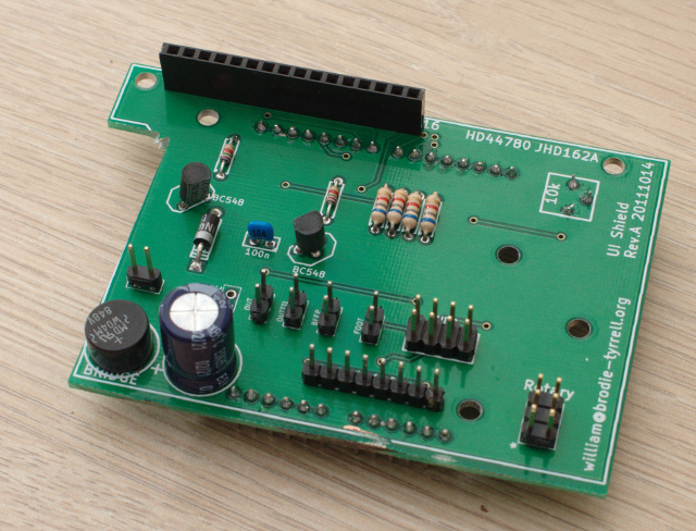
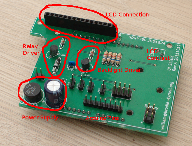
Assembled board, top:
With annotations as to component purpose
Assembled board, bottom:
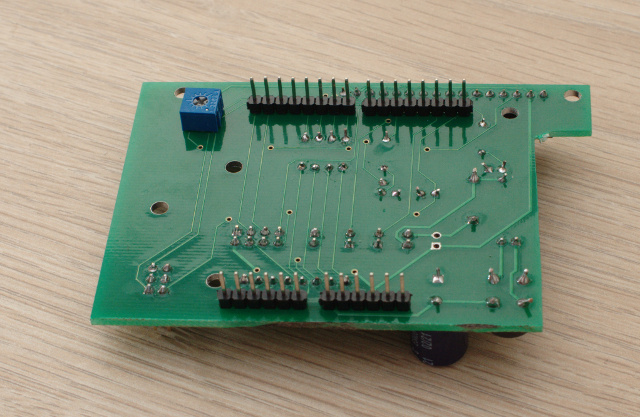
Note that the contrast-adjust pot (blue thing) for the LCD has been
mounted on this side for accessibility, and the pins for the Arduino
go here too because the board will stack on top of the Arduino.
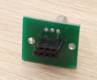
Rotary Encoder daughterboard:
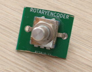
with pin header on reverse:
Complete assembled stack, showing Arduino, new PCB and LCD:
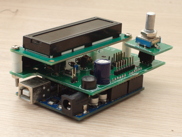
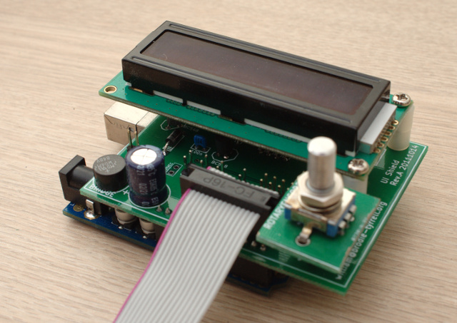
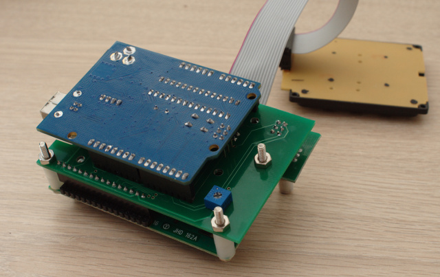
Note that you can also see the keypad attached by ribbon cable.
Beginning installation in aluminium case (forgive the clumsy Dremel-work):
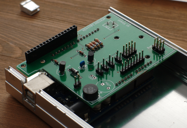
You can see here that I've removed the power-filter capacitor (this
instance doesn't use it because it depends on USB-power) in order to
clear the keypad. It's very very tight in that case...
Showing how the PCB stacks line up to get the encoder at the right
height:
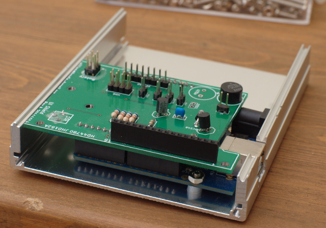
Installation of solid-state relay:
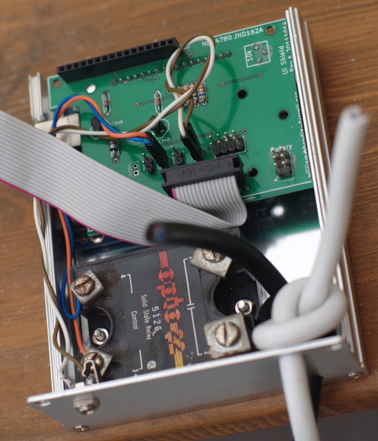
As you can see here, the case I chose is slightly too small for the
PCB, so I've had to trim the right hand side fairly heavily. It
doesn't encroach on any tracks, but it was a pretty ugly hack to
cram it in there. Similar trimming of the rotary encoder PCB was
required and that came very very close to the pins.
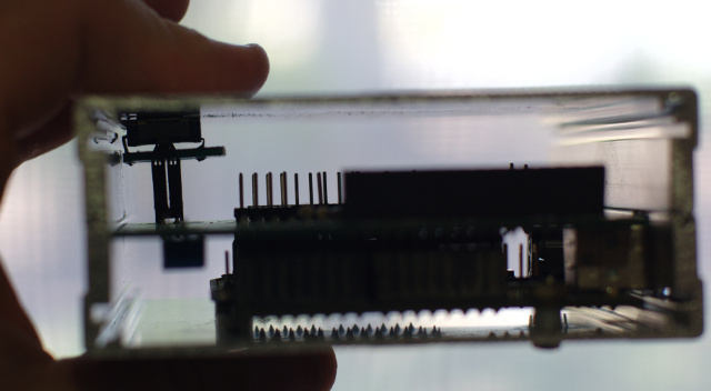
Finally, the completed item:
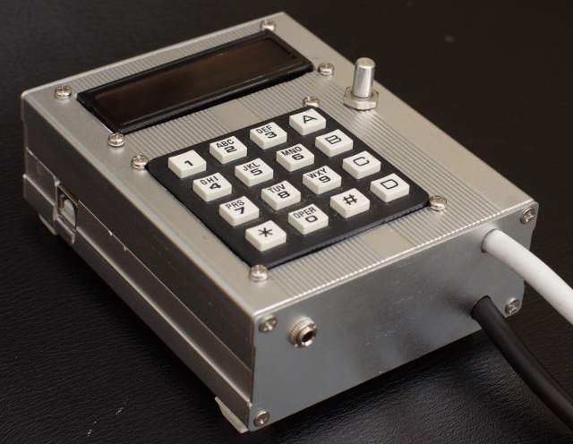
The 3.5mm port you can see at front-left is for attaching the
foot-switch. It is connected in parallel with the push-switch of
the rotary encoder.
I originally intended for the case to have a male/female pair of IEC sockets and an internal power supply transformer but it was nowhere near large enough to accommodate all of that. This particular instance therefore depends on an external USB power supply and the mains connections are flying-leads.