PWM/PID Fan Controller
This webpage shows how you can build a fan controller for an audio amplifier that modulates fan speed and noise according to the power currently being dissipated. When you're listening quietly, the fan will be silent and when you crank the volume up, the fan will respond just enough to keep the amplifier cool.
While designed for amplifier-cooling, this board can be repurposed to do PWM/PID temperature control of just about anything, has an opto-isolated input and a few auxiliary 12V outputs that can be used to switch other loads via relays.
If you build this, please contact me (email address is in the headers of all the source files) as I'd like to have some idea of how many of these are out there. Of course if you have suggestions or bug reports, please send them in too.
Why a fan controller?
Amplifiers dissipate heat. In the simplest case, you can use a large passive heatsink and it will be completely silent. However, if you need to pack a number of powerful and/or inefficient amplifiers into a small space, like a rack cabinet, then forced-air cooling is likely to be necessary.
Fans make noise, so it's best to run them as slowly as possible. Amplifiers can get warm but if they get too hot, they will fail. The nice thing is that for most amplifiers, the amount of power they dissipate is about proportional to their average output power: they run cool at low volume and require greater cooling at higher volume. It's therefore useful at least to build a thermal controller which will run a fan only just fast enough so that the amplifier doesn't cook and your fan is no louder than it strictly needs to be.
Semiconductors carrying minimal current don't mind being hot, but they have reduced safe operating area so it's best to keep them cool if you're asking for significant power from the amplifier. That means it's OK for an unloaded amplifier to run fairly hot but if you start working it hard, you might want to reduce its temperature. Assuming we're talking about audio amplifiers that are really loud when pushed hard, they will mask the fan noise when running at higher power, so we can afford to run the fan much harder when the amplifier is loaded.
There are lots of very simple fan controllers available, e.g. they're built-in to some cheap fans, or you can get simple analogue kits that will vary fan-speed according to air temperature in a fairly linear way. It would be much better though, to control the speed in a smarter way:
- monitor heatsink temperature directly, not air temperature
- monitor temperature at multiple locations, e.g. one sensor on each heatsink of a multi-channel amp
- use a better control-scheme than linear
- implement a two-mode (hot/quiet or cool/loud) control scheme
- have the system be somewhat tuneable and controllable
- provide overheat detection/prevention by integrating power controls
- give the power controls modern data/trigger interfaces
- maybe have a user-display interface for system setup/debugging
Concept of Operation
The fan controller is responsible for receiving a power-on signal from an external source, e.g. a user-switch or an electrical signal from a master device. It spins up the fan to check that it's working, closes some MUTE relays (to prevent power-on thump) then turns on the amplifier power. After a bit, the MUTE relays are released and you get your music. The controller keeps things appropriately cool until you tell it to turn off again or the cooling system fails, in which case it should shut-down cleanly before serious damage occurs.
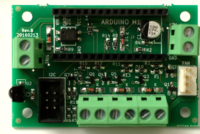
Construction
The smarts for the controller are in software running on an Atmel ATmega328P AVR, otherwise known as an Arduino Nano.
The system is powered from an always-on 12V DC supply; that supply runs the microcontroller as well as power-switching relays and the cooling fan. When the system is "off", the microcontroller is still running and waiting for a remote signal but the amplifier's main power supply is shut down.
Cooling is performed by a 12V, 4-wire (PWM) computer fan. They're becoming near-universal in PCs and therefore very affordable. 80mm and 120mm models with decent airflow capacity (at max speed) and practically-silent operation (at min speed) are readily available.
DS1621 sensors are each on small daughterboards, connected via a 6-wire ribbon cable that carries I2C and an overheat signal. You can have up to 8 of them connected to a single fan controller. Each sensor is intended to be bolted lightly to a heatsink with a small aluminium spacer and some thermal compound.
DS1621 sensors are a bit expensive and a bit annoying in form-factor, but they are chosen for safety in the face of software failures. A simpler sensor like the DS18B20 would be cheaper and probably easier to mount, but the DS1621 has a programmable hardware output signal that is activated on overheat.
System safety should not depend on software, i.e. in this case the system must still shutdown cleanly even if the software has crashed. To do this, the overheat signals from all of the sensors are combined so that if any one sensor detects an over-temperature condition, the amplifier power is shut off. This shutdown mechanism overrides the software and therefore should safely shutdown the amplifier in the case of software failure that causes a cooling failure.
The external power-on trigger signal is opto-isolated and will work with any DC source between 5V and 12V.
A 38kHz infrared-remote receiver is included in the design but no software for it has been integrated yet. In principle, it could be used to turn the amplifier on and off or even adjust control-settings dynamically.
No user-interface is provided except for an LED on the arduino which is used to indicate faults. If the system fails, it uses flash-codes to indicate the nature of the failure. Because the controller has a readily-accessible I2C bus for the temperature sensors, it would be relatively simple to attach an I2C LCD or OLED display but that hasn't happened yet.
The control-scheme is a nested pair of PI (proportional-integral) loops:
- the inner loop sets fan PWM level to achieve the setpoint RPM from the outer loop,
- the outer loop chooses a fan RPM as a function of heatsink temperature in order to maintain the setpoint temperature, and
- a simple state-machine with hysteresis chooses a hot or cold temperature setpoint according to perceived amplifier power load.
The controller attempts to measure amplifier load by observing the required fan RPM to maintain the setpoint. If the RPM climbs beyond a threshold for over one minute, the amplifier is deemed to be under load and the cooler/louder setpoint is selected. Similarly once the load is reduced, the fan RPM will reduce and the controller will switch back to the hotter/quieter setpoint.
The controller has a FAIL mode, which it will enter if it detects the loss or failure of a temperature sensor, fan stall, or overheat. If the failure relates to hardware (sensor or fan), the controller will remain permanently in the FAIL state until rebooted. If the failure was a simple overheat, the controller will remain in the FAIL state until cooled and the power-signal is turned off, at which point it will return to the standby/off state.
Screw terminals are provided for the connection of MUTE and POWER relays. MUTE relays are assumed to be 12V reed relays drawing less than 100mA coil-current; the POWER relay is assumed to be a 12V cradle relay and can draw up to 1A coil-current.
Purchase or Download
Coming soon. Initially it will be just bare boards, but I hope to have pricing on a fully-assembled, pre-programmed version soon.
Yes, this is a primarily surface-mount board but the smallest parts are SOT23 and 0805 with extended pads. If you can do through-hole and have a pair of tweezers, you can solder this one too.